
Previous
Next
Compact Support Arm System 5065 | Light Load Control Panel Mount
Product Positioning:
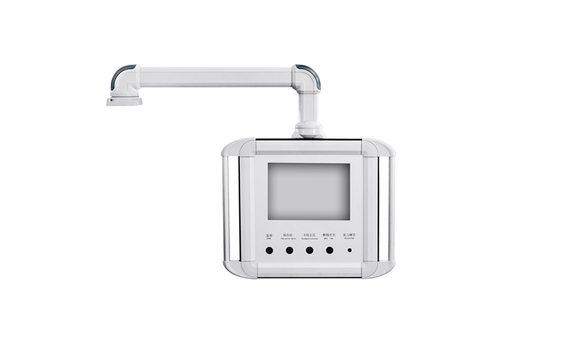
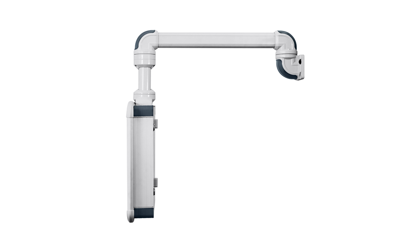
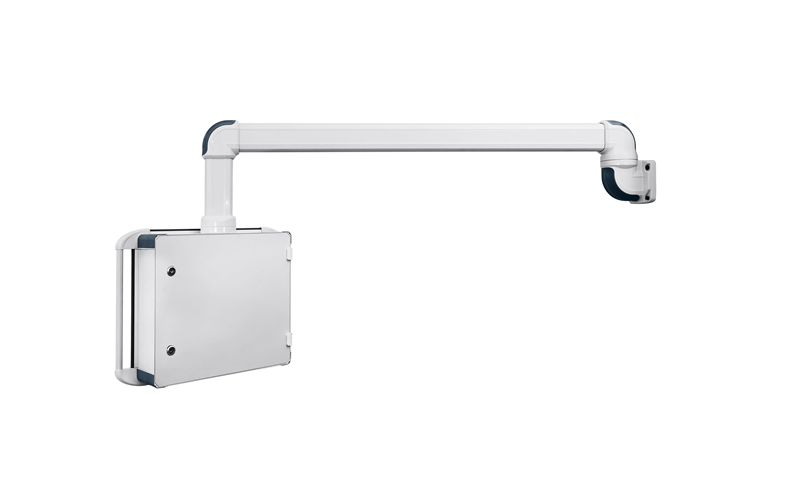
The 5065 Series is a compact support arm system designed for control panels with light loads. Its slim profile makes it suitable for applications with limited installation space, and its modular design ensures perfect harmony with other components.
Load Capacity :500 N
Applications:
1:Small control panels and operator terminals
2:Equipment with limited installation space
3:Light-load, short-reach support applications
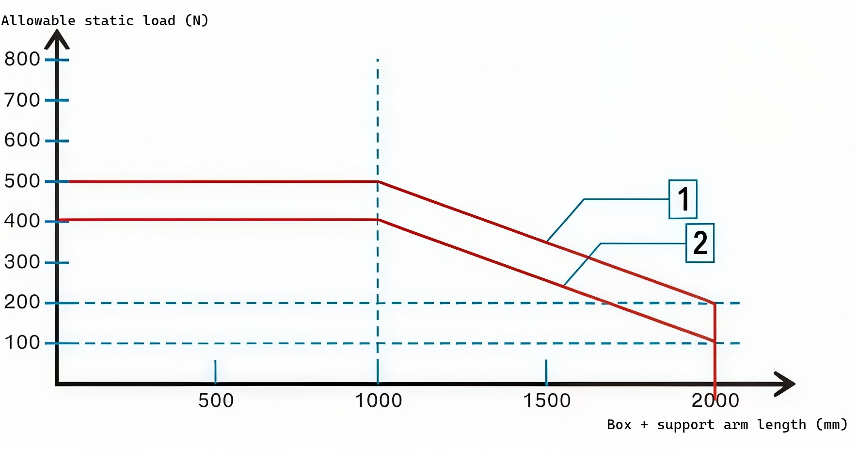
5065 Series Load-bearing capacity reference
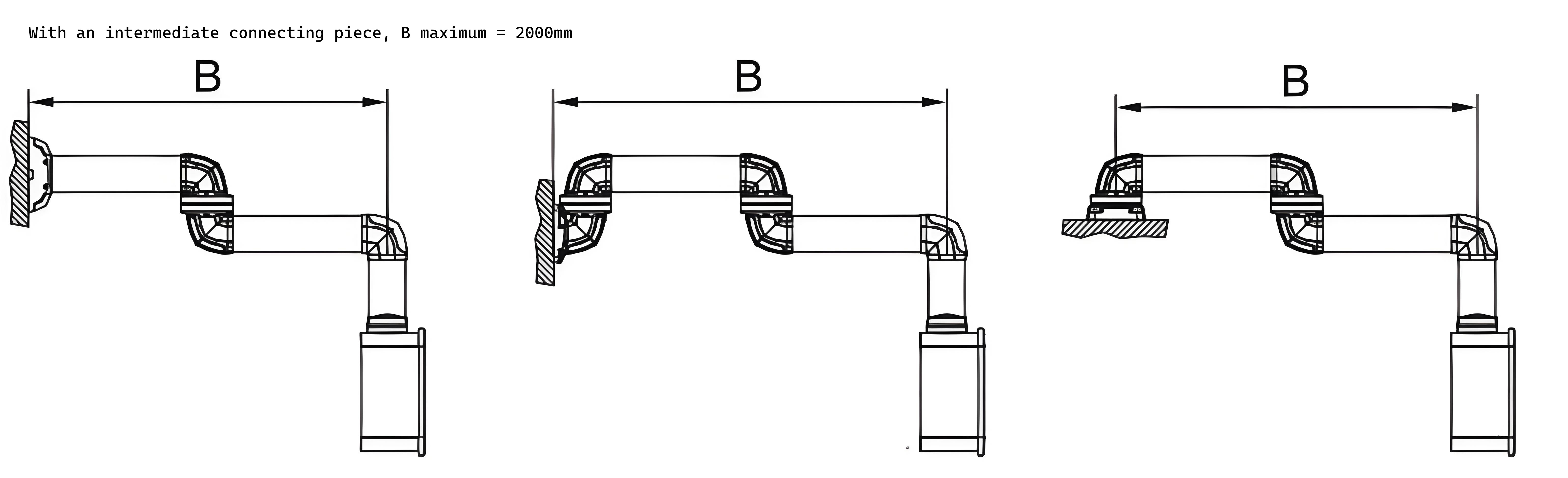
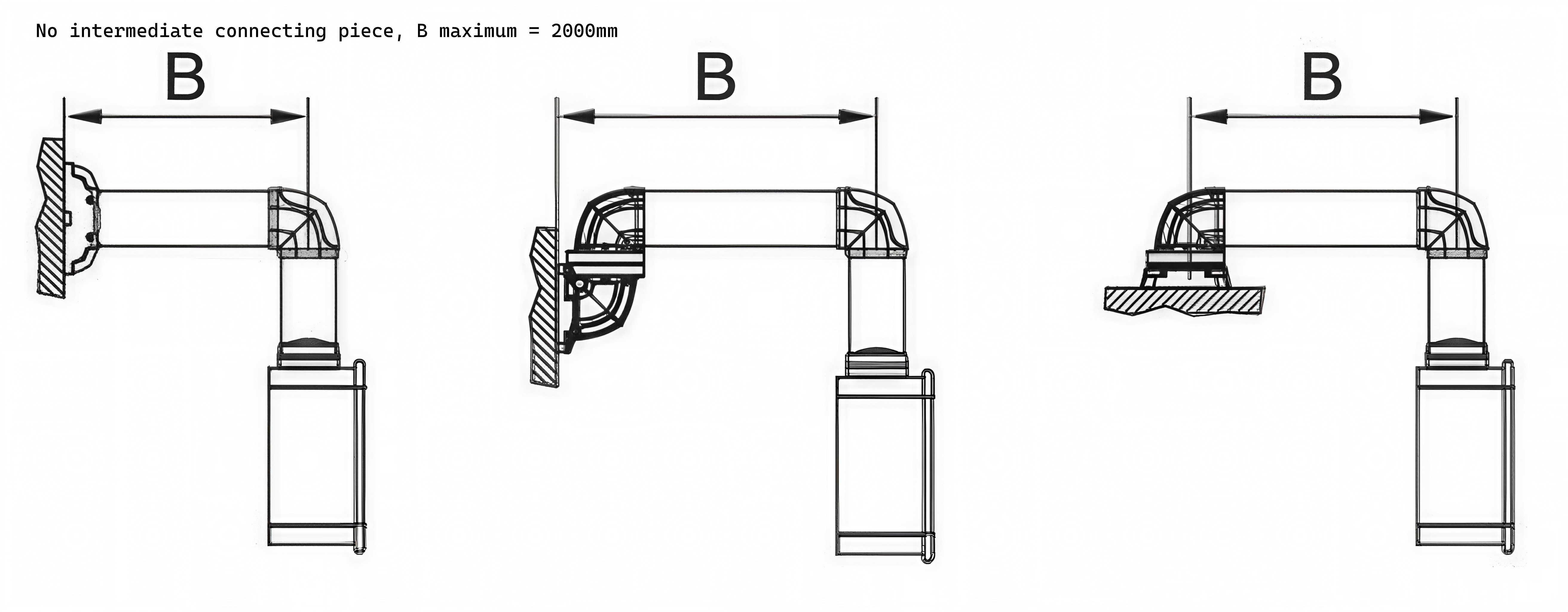
| Arm Length B (mm) | Allowable Load (N) - Without Intermediate Joint | Allowable Load (N) - With Intermediate Joint |
|---|---|---|
| ≤ 1000 | 500 | 400 |
| 1500 | 400 | 300 |
| 2000 | 200 | 100 |
When selecting the 5065 series, please note that the load capacity decreases as the arm length (B) increases. For applications requiring a longer reach (up to 2000mm), ensure the total weight of the control panel and its components does not exceed the corresponding load limit shown in the table above. If your required load exceeds these values, please consider our heavier-duty series.
| Feature | 5065 Series | 6095 Series | 75110 Series |
|---|---|---|---|
| Load Class | Light Load | Medium Load | High Load |
| Positioning | Compact support arm for small control panels | Medium-duty support arm for standard control panels | Heavy-duty support arm for large control panels |
| Max Load Capacity* | 500 N (≈51 kgf) | 1,000 N (≈102 kgf) | 1,500 N (≈153 kgf) |
| Typical Panel Weight* | Up to ~40 kg | ~40–60 kg | Over ~60 kg |
| Recommended Arm Length* | ≤ 1,000 mm | ≤ 1,500 mm | ≤ 2,000 mm |
| Profile Cross-Section | 50–65 | 60–95 | 75–110 |
| Standard Connection | Ø 130 mm | Ø 130 mm | Ø 130 mm |
| Material | Anodized aluminum profile | Anodized aluminum profile | Anodized aluminum profile |
| Protection Rating | IP54 | IP54 | IP54 |
| Mounting Options | Wall / base / machine | Wall / base / machine | Wall / base / machine |
| Cable Management | Integrated through hollow profile, cable/edge protection | Integrated through hollow profile, cable/edge protection | Integrated through hollow profile, cable/edge protection |
| Typical Applications | Small HMI panels, compact machine tools, space-limited workstations | Standard CNC machines, assembly lines, packaging equipment | Large CNC machines, heavy automation, multi-panel workstations |
*Load capacity and recommended panel weight depend on arm length, mounting type, and safety factor. For exact load-length curves, please refer to the specific product page or contact JDF.
Design & Selection Reference:
Mounting Configuration:
The 5065 series supports two mounting configurations: Type 1 (without intermediate joint) for maximum load capacity, and Type 2 (with intermediate joint) which reduces the load capacity by approximately 40%. Wall and base fasteners must not be used together with the intermediate joint.
 5065 Series Component Specifications & Dimensions:


More related options:
Heavy-Duty Support Arm System 75110 | High Load Control Panel Mount
Medium-Duty Support Arm System 6095 | Medium Load Control Panel Mount
5065 Series Drawing Downloads
Download 2D/3D CAD drawings and technical specifications for the 5065 Series Support Arm System.
FAQ
What is the maximum load capacity of the 5065 series?
The 5065 series is designed for light-load applications with a maximum load capacity of 500 N (approximately 51 kgf) at arm lengths up to 1000mm. As the arm length increases, the load capacity decreases proportionally. At the maximum arm length of 2000mm, the allowable load drops to approximately 200 N (approximately 20 kgf). This load-length relationship is based on the mechanical properties of the aluminum profile and the leverage effect at different extensions.
How do I select the correct 5065 model based on my control panel weight?
Follow these steps to select the correct 5065 configuration: (1) Determine the total weight of the control panel including all installed components. (2) Estimate the maximum arm length required for your application. (3) Refer to the load-length curve to find the allowable load at that arm length. (4) Apply a safety factor: divide the rated load by 2 for static applications or by 3 for dynamic or high-vibration environments. (5) If the calculated load exceeds the allowable load at the required arm length, consider the 6095 series for medium loads or reduce the arm length.
What is the difference between mounting with and without an intermediate joint?
The 5065 series supports two mounting configurations: Type 1 (without intermediate joint) and Type 2 (with intermediate joint). Type 1 provides higher load capacity because the arm connects directly to the wall or base mounting without additional joints, eliminating additional stress points. Type 2 uses one intermediate joint, which introduces an additional articulation point and reduces the overall load capacity by approximately 40% compared to Type 1 at the same arm length. Industry data confirms that intermediate joints reduce load capacity significantly. Each system should use the intermediate joint only once, and wall or base fasteners must not be used together with the intermediate joint.
What material is the 5065 series made of? What is the protection rating?
The 5065 series is constructed from high-quality anodized aluminum profiles (AL 6000 series). The anodized silver finish provides corrosion resistance and a clean, professional appearance suitable for industrial environments. The standard protection rating for the support arm system is IP54 according to EN 60529, which protects against dust ingress and water splashes from any direction. This rating is consistent with industry standards for modular suspension arm systems, where IP54 is the typical protection level for aluminum profile support arms with integrated cable management.
What mounting options are available for the 5065 series?
The 5065 series supports three primary mounting configurations: (1) Wall mounting — the arm is fixed to a vertical wall surface using a wall bracket. (2) Base mounting — the arm is mounted on a horizontal surface such as a machine frame or floor pedestal. (3) Machine mounting — the arm is directly attached to the machine structure. The standard support arm connection is Ø 130mm. Industry practice for HMI support arm systems includes wall, floor, and machine mounting options, allowing the arm to be adapted to different installation environments. Please note that wall and base fasteners must not be used together with the intermediate joint.
How does the 5065 series handle cable management?
The 5065 series features integrated cable management through the hollow aluminum profile. The profile's internal channel accommodates power and data cables, protecting them from mechanical damage and maintaining a clean appearance. Industry practice for modular suspension arms includes sufficient cable capacity within the profile to manage power and data cables, integrated USB ports, and additional peripherals. The cable entry point is located at the wall or base mounting end, with the cable routed through the profile to the control box connection point. This design eliminates external cable clutter and reduces the risk of cable damage during arm movement.
What is the difference between the 5065 and 6095 series? How do I choose?
The primary difference is load capacity and cross-section size. The 5065 series is a compact light-load support arm with a maximum load capacity of 500 N, designed for small control panels and space-constrained installations. The 6095 series is a medium-load support arm with a larger profile cross-section and higher load capacity, suitable for larger control panels and longer arm extensions. As a general guideline: if the total control panel weight (including components) is under 40 kg and the arm length is under 1000mm, the 5065 series is typically suitable. If the panel weight exceeds 40 kg or the required arm length exceeds 1500mm, consider the 6095 series. For heavier loads, the 75110 series is recommended.
What is the operating temperature range of the 5065 series?
The 5065 series is designed for standard industrial environments with an operating temperature range of -20°C to +70°C (-4°F to +158°F). This range covers the majority of indoor industrial applications including machine shops, assembly lines, packaging facilities, and process automation environments. For applications requiring operation outside this range, or for clean room or washdown environments, please contact JDF for custom solutions.